6 How to start
6.1 Make all necessary connections
Needless to say, the MUX-sensor system will not work unless the connections are done in the Con::nect Box! Follow The instructions in part 2.
6.2 Ready the peristaltic pump
To preserve the peristatic pump tumbing when not in use, the pump has a nice feature to press or release the tubing from the rollers. At reception of the MUX, the tumbing is not pressed against the rollers. Follow the video 6.1 below to do this.
Figure 6.1: How to press/release the peristaltic pump tubing against the rollers to activate/deactivate the pump
6.3 Install the flow through cuvette
At this time, it is important to install the cuvette in its cuvette holder and install the cuvette holder on the Spectro::lyser, as illustrated in the Figures below.
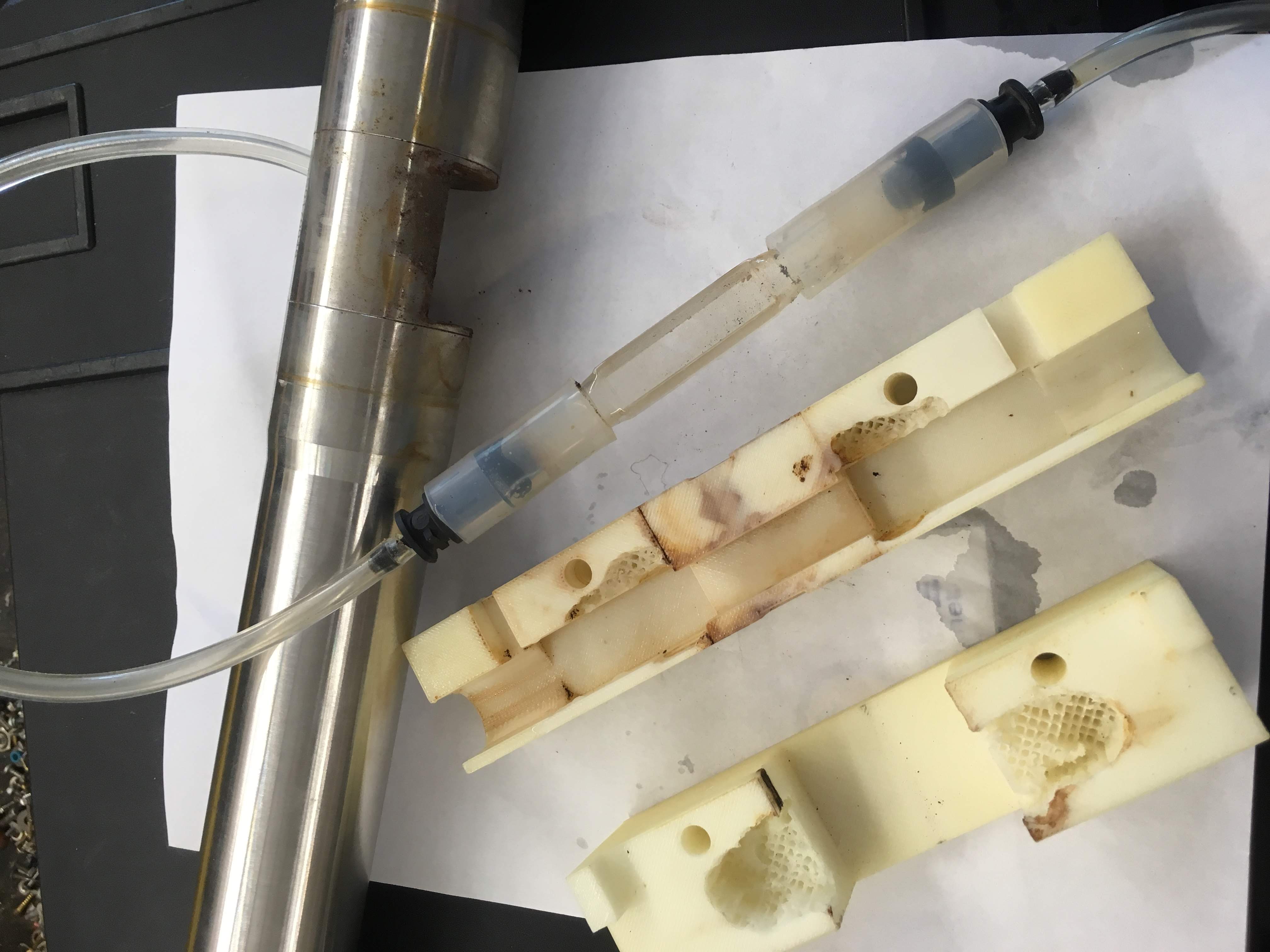
Figure 6.2: Flow through cuvette installed and its cuvette holder (not clean in the pictures here…)
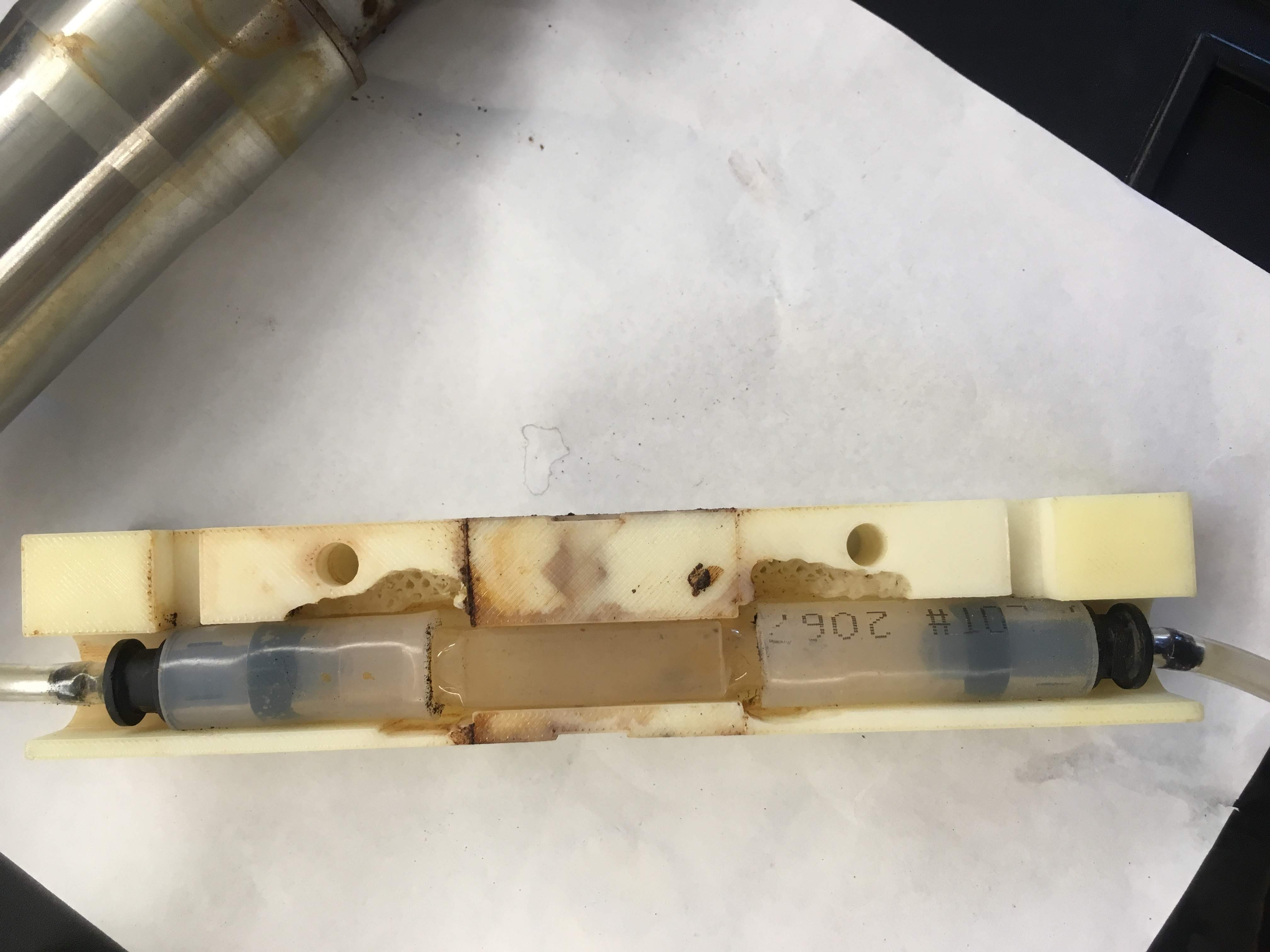
Figure 6.3: Flow through cuvette installed in its cuvette holder
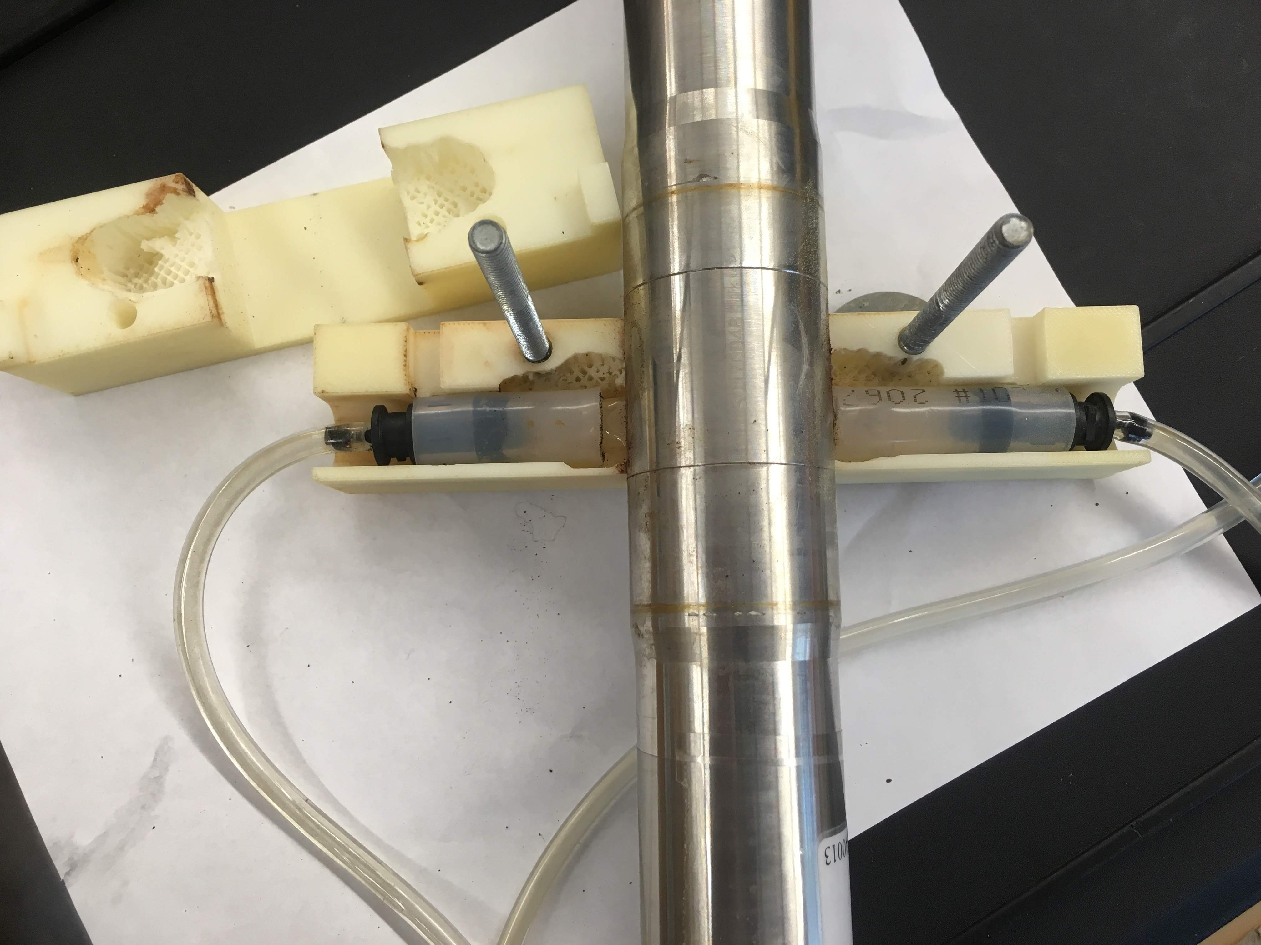
Figure 6.4: Flow through cuvette installed with the Spectro::lyser
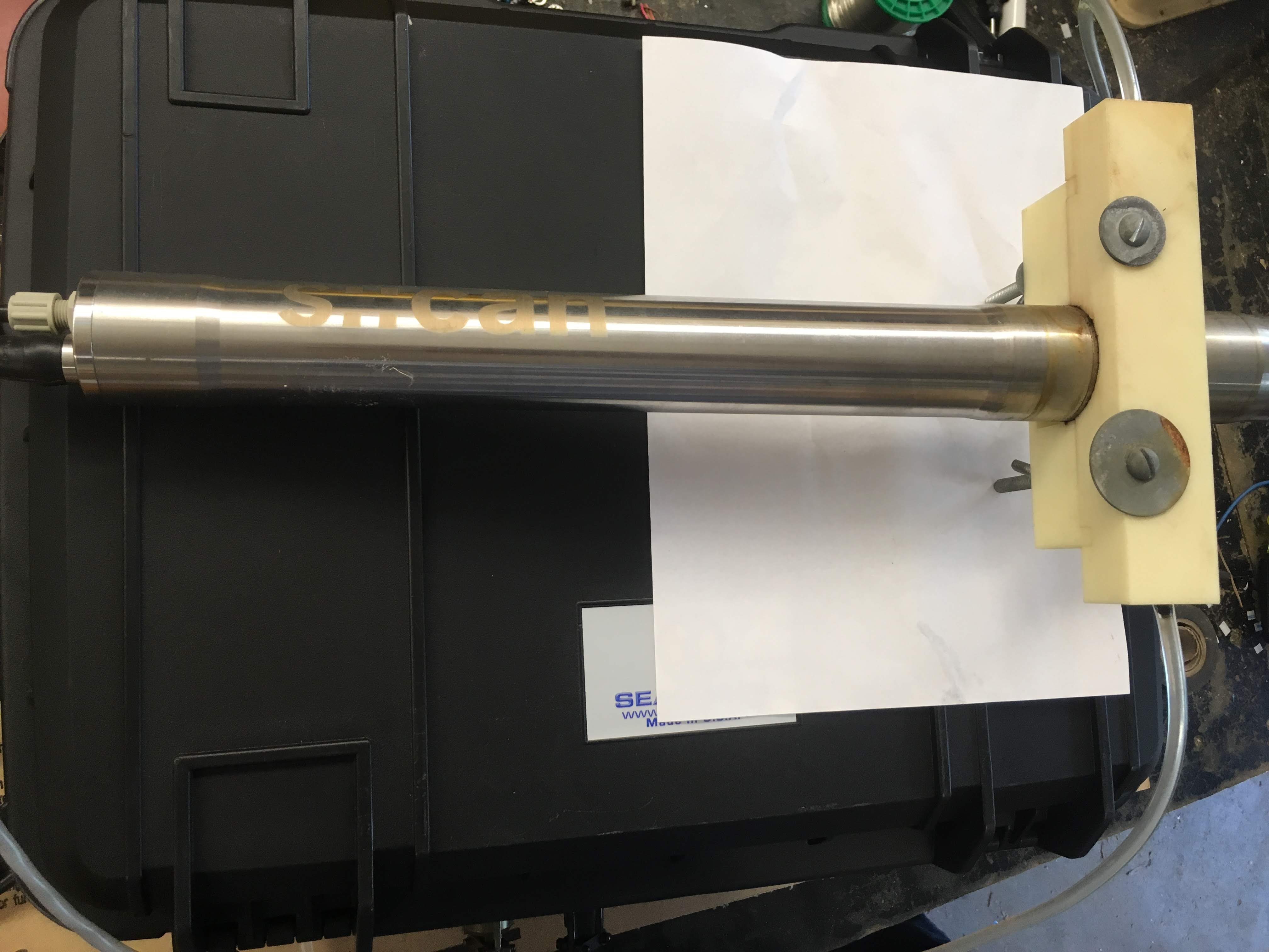
Figure 6.5: Full installation of the cuvette holder on the Spectro::lyser
6.4 Configure the Spectro::lyser for cuvette
For this, you need to log on to your spectro::lyser as ‘Service’ as illustrated below, and use the password Hermine. Now, you need to be extremely careful at what you are doing at this point becaus any number you might change might affect the proper functioning of the instrument!
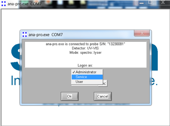
Figure 6.6: Log on the spectro::lyser as Service
Now, go to Extra/Configuration as shown on the figure below.
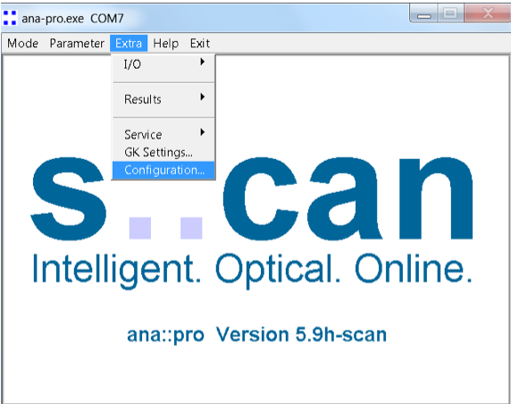
Figure 6.7: Go to Extra/Configuration
This will take you to the core of where all the parameters of the spectro::lyser are stored. Again, this is a danger zone so be careful at what you modify or not. So there are two parameters that you can change here as a first step. Go on the top right corner of the screen and change the Path (highlighted in red ellipse) to “Cuvette”. Now, the pathlength value is stored at the middle left of the screen (highlighted in red ellipse). You can see on the figure below that the value we have here is a 4 mm although we are actually using a 10 mm pathlenght cuvette. This is where it is a bit of an art and things are not fully clear from S::CAN. It is our understanding that the light bulb energy will automatically adjust to the ‘cuvette’ mode and the pathlength we are giving it. This suggests that with lower pathlength values, the light energy should be adjusted lower since there is less ‘thickness’ of water for light through which to travel. But we are not sure this always really works. In all cases, our experience has been that with the configuration used in the figure below, we have had good success in getting the ‘global calibration’ to calculate reasonable nitrate and DOC concentrations. We therefore recommend to use this configuration as a starter. Should the global calibration still not calculate reasonable values, our suggestion is to use 0.01 m (or 10 mm) as pathlength.
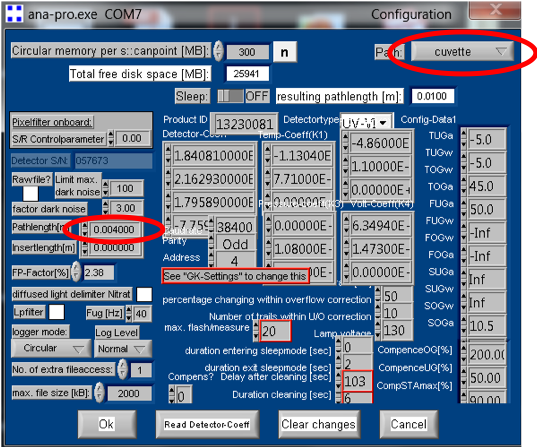
Figure 6.8: Go to Extra/Configuration
Then log off and log back on as administrator.
6.5 Turn the MUX on
To turn the MUX on, put the top left swith to the ON position. When the Spectro::lyser is connected to the Con::nect box, the MUX starts its routine identifying a XXXX-MUX.txt file, and then identifies a .fp file. If the SD card is missing, there will be an NA file for the XXXX-MUX.txt file. If the Spectro::lyser is not connected, there will be an NA file for the .fp file. See video 6.9 for illustration
Figure 6.9: Illustration of initialization phase
6.6 Test the MUX in the lab
We recommend that before going out to the field, the user should test the MUX in the lab to get acquainted with the MUX, without having to deal with the field constraints. The contraption to connect the MUX the Spectro::lyser in the field should be tested in the lab first. It is also the time to build/test a sample spool.
It is the time to test the configuration the user is expected to have in the field. It is at that time to test the config.txt file that is expected to be used. Only the pump times will have to be adjusted in the field afterwards. It is best to test the MUX over several days in the lab to get acquainted with the files generated on the SD card.
6.7 Install and test the MUX in the field
6.7.1 Install all hardware to length
When the lab tests have been successful, it is time to install the MUX-sensor system in the field with all the tubing cut to length. It is crucial that the final lengths be correct to test the proper <PUMP TIMES>, <MEASUREMENT TIMES>, and <PURGE TIMES>.
Make sure the intakes for all have screen or mesh size not larger than 1.2 mm. We have seen the pump stall because of large particles that got stuck in the peristaltic pump tubing.
6.7.2 Use manual pumping feature to obtain you pump and purge times
For that, the MUX has a manual pumping and manual purging feature. At the bottom right end of the control box, there is a toggle switch with three positions (Figure 6.10): up for FOR or forward pumping, middle for neutral when not used in manual pumping mode, and down for REV or purging. Make sure you keep this toggle in neutral or middle position for all other use of the MUX.
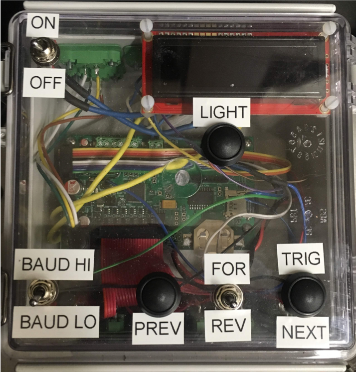
Figure 6.10: Control box panel display
When manual pumping or purging, a timer keeps track of time and gives the user an opportunity to time all the desired pumping and purging times, to be programed later in the config.txt file. To switch from valve to valve, press the PREV button. An example is provided in the following video 6.11.
Figure 6.11: Illustration of the manual pumping features
6.7.3 Manually trigger the MUX
Once you have recorded and implemented the timing in the field, it is time to trigger the MUX manually by pressing the TRIG button. A sampling sequence will then start with the first valve on the config.txt file. Adjust all timing accordingly and if needed after you observed how the sampling sequence works.
6.7.4 Change clock
To change the clock, press together at the same time the LIGHT, PREV, and NEXT buttons. Advance on the screen using the PREV, and NEXT buttons. Change the values turning the switch up and down. The instructions are further illustrated on the video 6.12.
Figure 6.12: Illustration of how to change the clock