4 Programing the MUX
4.1 The SD card in the control box
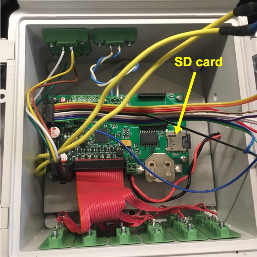
All the instructions for programing the MUX are consigned in the config.txt file, itself located on the micro SD card. The SD card can be retrieved by opening the control box. One may use the macro SD card adapter provided to read the SD card on a computer (Figure 4.1).

Figure 4.1: Location of the SD card in the control box of the MUX
4.2 The config.txt file
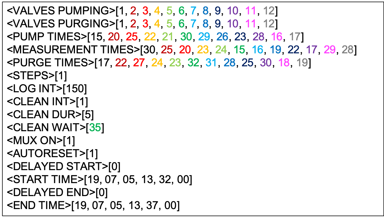
All the instructions for the sampling sequences are provided in the config.txt. A typical basic config.txt file looks like in Figure 4.2 below. In this particular example, there are 12 valves activated in a sampling cycle ranked in increasing order from 1 to 12. The order of the valves can be completely interchanged and the sampling cycle will go followin the prescribed order.

Figure 4.2: Typical config.txt file where 12 ports are activated, with no automatic rinsing
4.2.1 Programming the MUX sampling sequence without automatic rinsing
The commands for the sampling sequences for each sampling cycle are given in the first 6 lines of the config.txt file (Figure 4.3). Each variable between <...> defines the name of the variable used in the program, and all numbers between [...] define the array of values to be used. The values in one array correspond to all the values necessary for a sampling cycle.

Figure 4.3: The commands for the MUX sampling sequence timing are provided in the first 6 lines of the config.txt (12 ports are activated, with no automatic rinsing)
<VALVES PUMPING>defines the list and its order of the valves or port which will be activated during pumping of the sampling cycles. In the example of Figure 4.3, the sampling cycles inclues all valves from 1 to 12 in that order.<VALVES PURGING>defines the list and its order of the valves or port which will be activated during the purging phase of each sampling sequence of the sampling cycle. In the particular example of Figure 4.3, all water is purged back to its source as the same valve is used during pumping and purging.<PUMP TIMES>defines the array of values in seconds that will be used for the pumping in each sampling sequence corresponding to the pumping valve activated.<MEASUREMENT TIMES>defines the array of values in seconds that will be used for each sampling sequence and corresponding to the activated valve.<PURGE TIMES>defines the array of values in seconds that will be used for the purping in each sampling sequence corresponding to the purging valve activated.<STEPS>[1]means that there is no automatic rinsing. Technically, it defines the fact that the program will read each array and each cleaning signal will activate the next[1](one) value in the array. In other words, the program will read the next value in the array to be used upon a cleaning signal (more details later).
For illustration purposes, the text of the config.txt file have been colored. In the current example (Figure 4.3), in the sampling cycle, the first sampling sequence starts with pumping from valve 1 for 15 seconds, waits for 30 sec for the Spectro::lyser to do its measurement, then purge to through the same valve 1 for 17 seconds, i.e., 2 seconds more than pumping to remove as many drops as possible. Because the <STEPS> is set to 1, the MUX waits for the next Spectro::lyser cleaning signal to start its next sampling sequence.
By analogy, the 7th sampling sequence starts with pumping from valve 7 for 29 seconds, waits for 16 sec for the Spectro::lyser to do its measurement, then purge to through the same valve 7 for 31 seconds, i.e., 2 seconds more than pumping to remove as many drops as possible.
Notice that for all activated valves,
<PUMP TIMES> + <MEASUREMENT TIMES>is always equal to 45 seconds, and the 45 seconds corresponds to the longest pumping time (30 sec, corresponding to valve 6 in the example), plus 5 seconds of no pumping for all gas bubbles to settle, plus 9 seconds for the Spectro::lyser measurement to take place. The current setting suggests that the MUX would start its purging not even one second after the last beep of the Spectro::lyser measurement… That would work, but honestly there is advantage to do that. So adding several seconds more in the measurement timings would probably be more judicious and safer to make sure water is still in the cuvette for the full measurement.Also notice that the
<PUMP TIMES> + <MEASUREMENT TIMES>is equal to the<CLEAN WAIT>(Figure 4.2) value minus 5 seconds corresponding to the minimum of time for bubbles to settle for the longest pumping time (more details below)
4.2.2 Programming the MUX sampling sequence with two automatic rinsing, and a waste port
The next example illustrates more complicated options. The user wants to use points 10, 1, 3, 8, 9, 2 in that order in a sampling cycle and wants to add an air tracer measurement. The user does not want to purge water back to the sampling point, but rather, wants to purge all water to a waste port, which incidently can be used for lab sampling purposes. The user also wants to use two automatic rinsing, the first one with acid where acid would stay in the cuvette for 55 seconds to leave enough reaction time, and the second one with DI to rinse the acid off.
The MUX could be programed as illustrated in Figure 4.4 below.

Figure 4.4: Programing for 6 ports and an air measurement, purging to waste, and two automatic rinsing
- Notice that
<STEPS>value is set to 3. This means that the MUX sampling sequence will be activated by the cleaning signal every 3 values of the arrays (the text in black in Figure 4.4). In between, the green and red values, are automatically activated during the sampling sequence, and correspond here to the two rinsing desired. The green values corresponds to the values for the acid rinse, and the red values correspond to the DI rinse. - The activated sampling ports (other than rinsing) of the sampling cycle are defined in the
<VALVES PUMPING>array and appear in black in Figure 4.4. Their list is thus 10, 1, 3, 8, 9, 2, and 13. The last one, 13, corresponds to the waste port open to the atmosphere, which means that it can be used for ‘air tracer measurement’. - The port used for purging of the sampled points (other than rinsing) also appears in black in the
<VALVES PURGING>array, and is always 13. - The pump times, measurement times, and purge times for the sampled points are illustrated in black, respectively, in the
<PUMP TIMES>,<MEASUREMENT TIMES>, and<PURGE TIMES>arrays (Figure 4.4) - The acid rinse will be pumped and purged from and to port 11 everytime. There often no need to purge acid to waste. Although, the low strength of the acid would not damage the environment, it is preferable to purge back to its bottle to save acid. The dilution by water droplets will not affect acid strength and anti-fouling efficacy.
- To leave acid in the cuvette for 55 seconds, the user add 55 sec. in the
<MEASUREMENT TIMES>array. - The DI water rinse is always pumps from port 12 in the example from a designated DI water jar. In the example, the DI water is purged to the waste port 13. This implies that a lrge enough DI water container be used to have enough between field service intervals.
- The amount of time DI water stays in the cuvette does not matter as much as acid here and a value of 4 seconds has been chosen in the example.
- During the air measurements, the pumping and purging times are kept to a minimum (2 sec.) to minimize energy spending and peristaltic pump wear. The measurement time (black value) is set to 43 seconds to stay in sequence with the other sampling sequences although it could have been shortened as well.
4.2.3 The Spectro::lyser values in the config.txt file
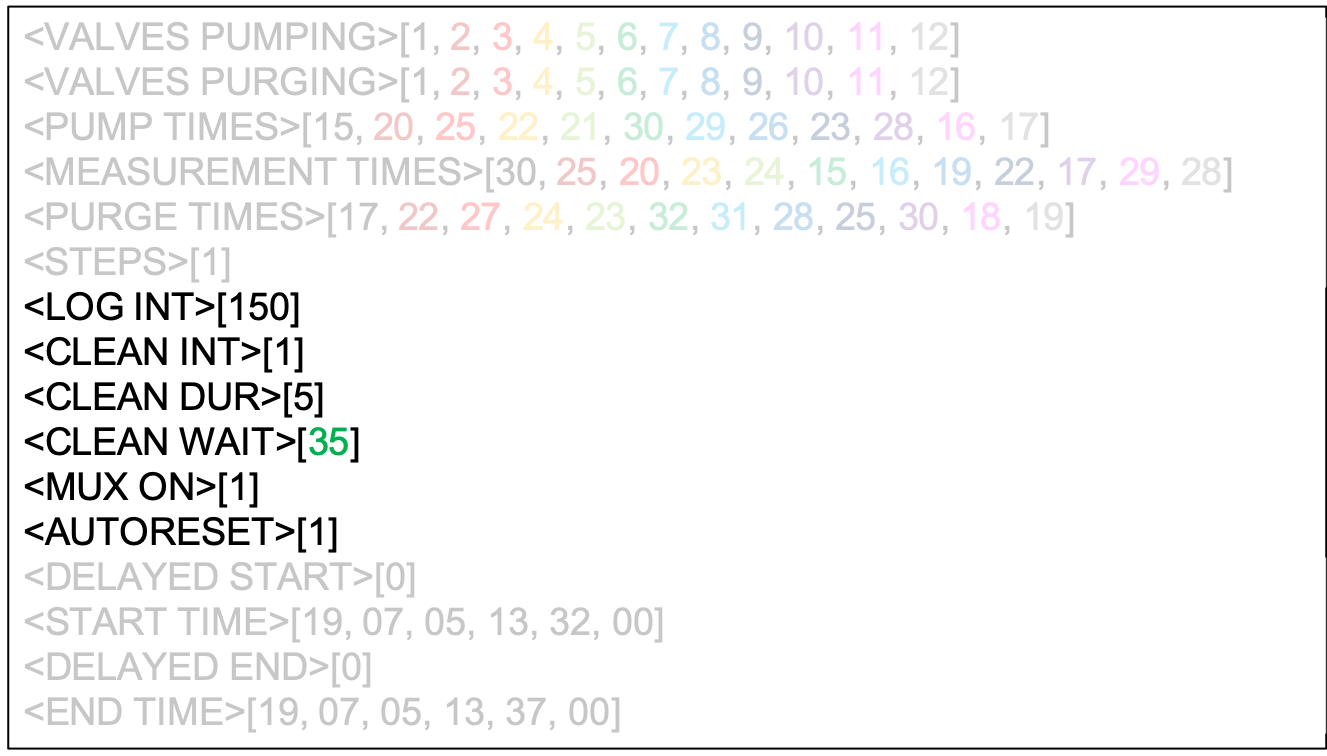
The next five lines in the config.txt file give instructions to the Spectro::lyser on the values to use when going into the logger mode (Figure 4.5).

Figure 4.5: The parameters in the config.txt to pilot the Spectro::lyser
<LOG INT>defines the interval in seconds, at which the Spectro::lyser will take a measurement and logs its value. It also corresponds to the interval at which the Spectro::lyser sends a cleaning signal, which in the end corresponds at the time interval between two sampling sequences. The time interval on each sampled point will be the recurring interval of a sampling cycle.<CLEAN INT>defines the number of logging intervals or measurements from the Spectro::lyser there are before it sends a cleaning signal. This does not apply to our use, as we want to have a cleaning signal sent everytime the Spectro::lyser takes a measurement. ALWAYS set it to 1.<CLEAN DUR>defines the number of seconds the 12V cleaning signal coming from the Spectro::lyser is on.<CLEAN WAIT>defines the number of seconds between the beginning of the cleaning signal and the first beep of the Spectro::lyser measurement. The duration of this value is linked to the pumping times, and must be equal, at least, to the longest pumping time of the sampling cycle, plus 5 seconds to leave time for air bubbles to settle.<MUX ON>has to be set at 1. It corresponds to a feature obsolete with the current version of MUX.<AUTORESET>this option defines whether the user wants the system to autorest at midnight everyday. We recommend to use this option (set to [1]), as it allows the MUX to clean up its memory. If the user prefers not to use this option, then set to [0].
4.2.4 Delayed start
In many situations, it might be of advantage not to start sampling when the users are in the field, but rather start at a later time. Similarly, the user might want to stop the system before being able to come to the field to retrieve data. This what the delayed start and end are for. If the user does not want the delayed start and end, set <DELAYED START> and <DELAYED END> to [0].
When the user wants a delayed start, set both <DELAYED START> and <DELAYED END> to [1]. The start time is defined in <START TIME> as [YY,MM,DD,HH,mm,SS]. When the user does not want the system to end until the next field visit, set the <END TIME> to several years later. An example is given below in Figure 4.6.

Figure 4.6: Example of delayed start on the config.txt file
4.3 Examples of config.txt files
Always make sure that there is the arrays in the <VALVES PUMPING>, <VALVES PURGING>, <PUMP TIMES>, <MEASUREMENT TIMES>, and <PURGE TIMES> all have the same number of values!!!
4.3.1 Sampling cycles with no rinsing
- 12 sampling ports in 1, 2, 3, 4, 5, 6, 7, 8, 9, 10, 11, 12 order.
- same purging ports
- Five minutes sampling sequence intervals
- 60 time resolution for each sampled point
<VALVES PUMPING>[1, 2, 3, 4, 5, 6, 7, 8, 9, 10, 11, 12]
<VALVES PURGING>[1, 2, 3, 4, 5, 6, 7, 8, 9, 10, 11, 12]
<PUMP TIMES>[15, 20, 25, 22, 21, 30, 29, 26, 23, 28, 16, 17]
<MEASUREMENT TIMES>[30, 25, 20, 23, 24, 15, 16, 19, 22, 17, 29, 28]
<PURGE TIMES>[17, 22, 27, 24, 23, 32, 31, 28, 25, 30, 18, 19]
<STEPS>[1]
<LOG INT>[150]
<CLEAN INT>[1]
<CLEAN DUR>[5]
<CLEAN WAIT>[35]
<MUX ON>[1]
<AUTORESET>[1]
<DELAYED START>[0]
<START TIME>[19, 07, 05, 13, 32, 00]
<DELAYED END>[0]
<END TIME>[19, 07, 05, 13, 37, 00]
4.3.2 Sampling cycles with one rinse
- 4 sampling ports in 1, 3, 5, 7 order, no tracer measurement (not recommended)
- one automatic (e.g., DI water) rinse on port 2
- same purging ports
- Three minutes sampling sequence intervals
- 12 time resolution for each sampled point
<VALVES PUMPING>[1, 2, 3, 2, 5, 2, 7, 2]
<VALVES PURGING>[1, 2, 3, 2, 5, 2, 7, 2]
<PUMP TIMES>[10, 5,10, 5,10, 5,10, 5]
<MEASUREMENT TIMES>[12, 3, 12, 3, 12, 3, 12, 3]
<PURGE TIMES>[10, 3, 10, 3, 10, 3, 10, 3]
<STEPS>[2]
<LOG INT>[180]
<CLEAN INT>[1]
<CLEAN DUR>[5]
<CLEAN WAIT>[12]
<MUX ON>[1]
<AUTORESET>[1]
<DELAYED START>[0]
<START TIME>[19, 07, 06, 06, 08, 00]
<DELAYED END>[0]
<END TIME>[19, 07, 06, 13, 37, 00]
4.3.3 Sampling cycles with one rinse
- 4 sampling ports in 1, 3, 5, 7 order, one air tracer measurement (recommended)
- one automatic (e.g., DI water) rinse on port 2
- All purging on port 13
- Three minutes sampling sequence intervals
- 15 time resolution for each sampled point
<VALVES PUMPING>[1, 2, 3, 2, 5, 2, 7, 2, 13, 2]
<VALVES PURGING>[13, 2, 13, 2, 13, 2, 13, 2, 13, 2]
<PUMP TIMES>[10, 5,10, 5,10, 5,10, 5, 2, 2]
<MEASUREMENT TIMES>[12, 3, 12, 3, 12, 3, 12, 3, 2, 2]
<PURGE TIMES>[10, 3, 10, 3, 10, 3, 10, 3, 2, 2]
<STEPS>[2]
<LOG INT>[180]
<CLEAN INT>[1]
<CLEAN DUR>[5]
<CLEAN WAIT>[12]
<MUX ON>[1]
<AUTORESET>[1]
<DELAYED START>[0]
<START TIME>[19, 07, 06, 06, 08, 00]
<DELAYED END>[0]
<END TIME>[19, 07, 06, 13, 37, 00]
4.3.4 Sampling cycles with one rinse
- 4 sampling ports in 10, 1, 3, 8, 9, 2, and one air (13) tracer measurement (recommended)
- two automatic, e.g., acid or port 11, followed by DI water rinse on port 12
- All purging on port 13, but for acid back to port 11
- Because of the two rinses, the interval between two sampling sequences has to be a bit longer, in fact longer than the summation of the (pumping time + measurement time), the acid (pumping, stay in cuvette, purging) times, and the DI water (pumping, stay in cuvette, purging) times. That sum is equal to 164 seconds. So technically, one could set the log interval to 180 seconds. However, in practice, this would mean that the MUX would be pumping and purging a lot of the time, drawing lots of power and wearing out the peristaltic pump tubing. The user must also assess whether 30 min or hourly data is in fact plenty enough.
- Five minutes sampling sequence intervals
- 35 time resolution for each sampled point
<VALVES PUMPING>[10, 11, 12, 1, 11, 12, 3, 11, 12, 8, 11, 12, 9, 11, 12, 2, 11, 12, 13, 11, 12]
<VALVES PURGING>[13, 11, 13, 13, 11, 13, 13, 11, 13, 13, 11, 13, 13, 11, 13, 13, 11, 13 , 13, 11, 12]
<PUMP TIMES>[28, 14, 14, 15, 14, 14, 25, 14, 14, 26, 14, 14, 23, 14, 14, 20, 14, 14, 2, 2, 2]
<MEASUREMENT TIMES>[17, 55, 4, 30, 55, 4, 20, 55, 4, 19, 55, 4, 22, 55, 4, 25, 55, 4 , 43, 2, 2]
<PURGE TIMES>[29, 17, 16, 1, 17, 16, 3, 17, 16, 8, 17, 16, 9, 17, 16, 2, 17, 16 , 20, 14, 14 , 2, 4, 4]
<STEPS>[3]
<LOG INT>[300]
<CLEAN INT>[1]
<CLEAN DUR>[5]
<CLEAN WAIT>[33]
<MUX ON>[1]
<AUTORESET>[1]
<DELAYED START>[0]
<START TIME>[19, 07, 06, 06, 08, 00]
<DELAYED END>[0]
<END TIME>[19, 07, 06, 13, 37, 00]