2 How to hook things together
2.1 The different parts
The version you have received works with a S::CAN spectro::lyser, a Con::nect box, a power supply cable connected between a battery or a AC to DC transformer, a 12V battery (+ solar panel for long term deployment) or a AC to DC transformer, a 6-pin and a 2-pin cables provided with the MUX, and the MUX itself. You need all these parts for things to work properly.
We use only 4 of the cables of the 6-pin cable. This cable is used to catch the cleaning or valve signal from the Spectro::lyser, which we later use trigger the MUX sampling sequence, and, to obtain the measurement data through the RS485 connection and communication protocol.
We use the 2-pin cable to power the MUX. Honestly, we could have used the 6-pin cable and use all 6 cable to do, power, cleaning signal, and the data transfer, but by default, we like to keep a cable dedicated to power.
2.2 Connecting with the Con::nect Box
All wires to the MUX are connected to the Con::nect Box. To use with the MUX, we use the left panel of the Con::nect Box (Figure 2.1).
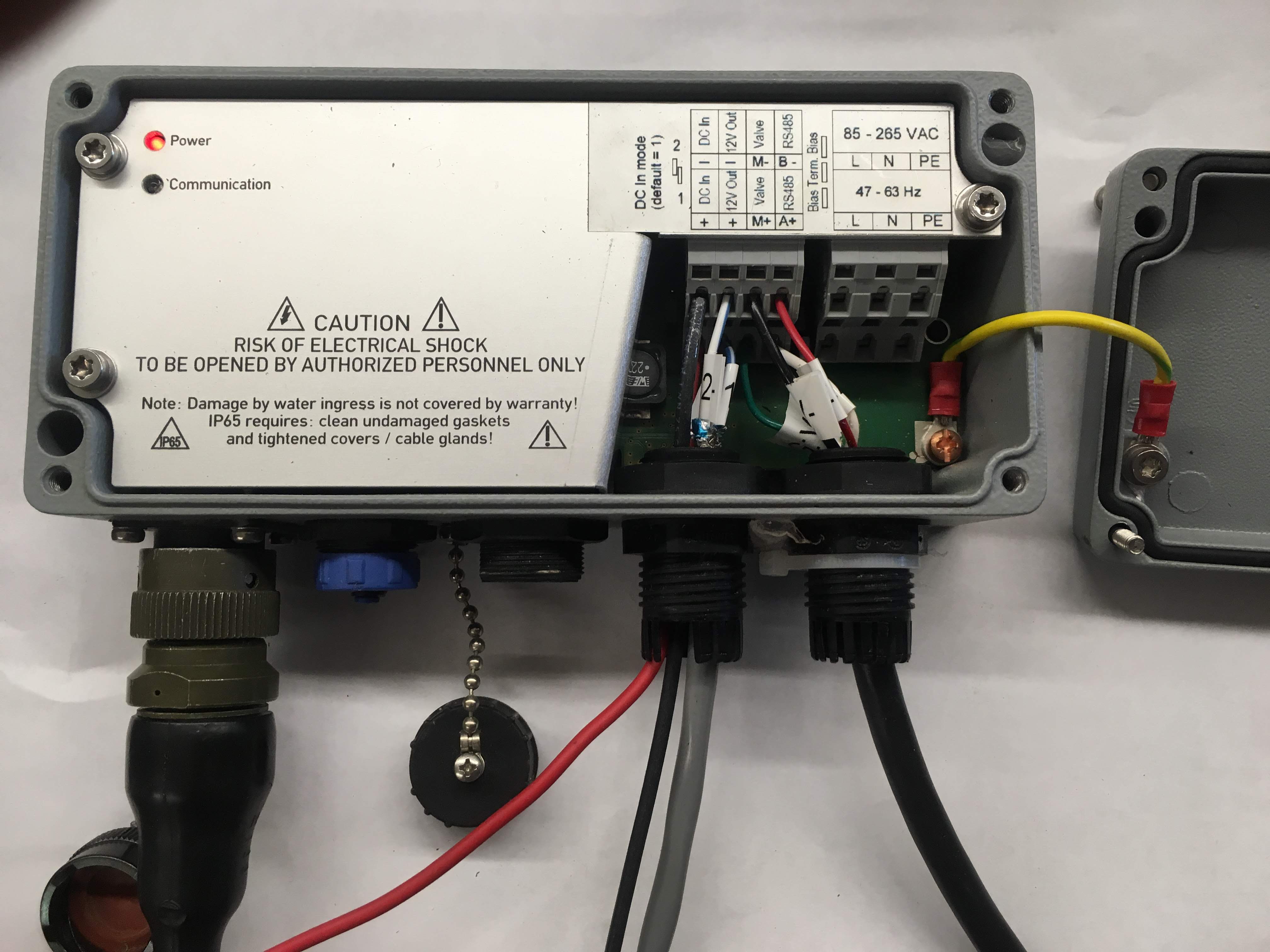
Figure 2.1: picture of the connecting capabilities inside the Con::nect Box
2.2.1 Powering the Con::nect Box
At the most left side, the user connects the wires either connected a 12V battery, or to an AC to DC adapter, which delivers 12V. This is referred to as ‘DC In’ on the Con::nect Box label (Figure 2.1). By convention, the positive wire is normally red and the negative wire, black. The black or negative wire is at the top or right of the label, and the red or positive wire is at the bottom (not really visible on Figure 2.1). Make sure you use at least 14 gauge for these wires, to be on the safe side.
All the Con::nect Box connections are done using spring-loaded terminal. You need to use a fine screwdriver and insert it on the top part of the terminal (yellow arrows on Figure 2.2), gently push or rotate down to open the spring-loaded connection located below (magenta arrows on Figure 2.2). While open, insert the wire as deep as you can to obtain the best and secure connection, while still leaving the plastic sheathing out. Make sure the free wires are not longer than 4 mm, however, otherwise free wires will be stay out and that is not ideal. After you have inserted the wires, make sure you pull on the wire. If it comes out easily, do it again until it is hard to pull on it. Also, always insert the bottom wires first.
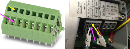
Figure 2.2: Spring-loaded connections for the Con::nect Box
The three other connection types include ‘12V out’, ‘Valve’, and ‘RS485’, and we use all three with the MUX.
2.2.2 Powering the MUX
The MUX is powered by the ‘12V out’ connection. The Con::nect Box provides a source of 12V power to other instruments that might be connected to it and we are taking advantage of this system to power the MUX. For that you will use the 2-pin cable as illustrated in Figure 2.3 below.
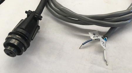
Figure 2.3: 2-pin cable to provide 12V DC power to the MUX, with the blue wire as ‘+’ and the white wire as ‘-’
The blue wire corresponds to the positive or “+” and the white wire corresponds to the negative or ‘-’. As illustrated in Figure 2.4, insert the blue “+” wire at the bottom or left connection, and the white “-” wire at the top or right connection of the ‘12V out’ terminal.
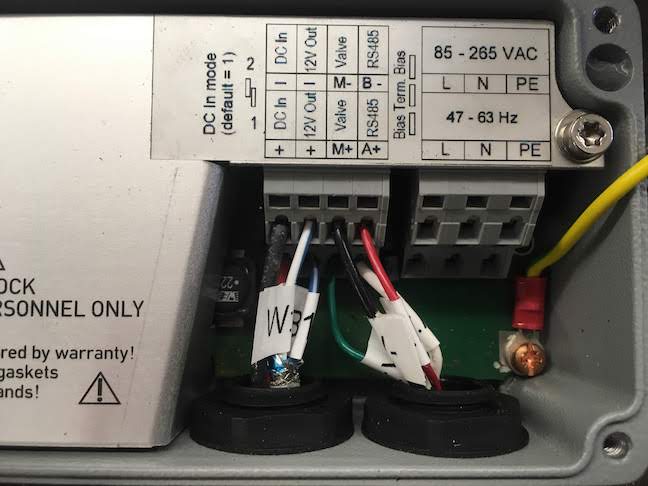
Figure 2.4: 2-pin cable to provide 12V DC power to the MUX, with the blue wire as ‘+’ and the white wire as ‘-’
2.2.3 Connections to Trigger the MUX
The Con::nect box has a connection through which it can send a 12V signal for a specified amount of time. Actually, it is the spectro::lyser that sends the 12V. Originally, this was used to open an air valve to send a burst of compressed air to clean up the optics. Later it has been used to activate an automatic brush, also to clean the optics. We are using this feature to start a sampling sequence from the MUX. When at idle, the MUX is listening to such a 12V signal, and upon receiving this signal the MUX starts its sampling sequence.
For this we use the black and green wires of the 6-pin cable (Figure 2.5).
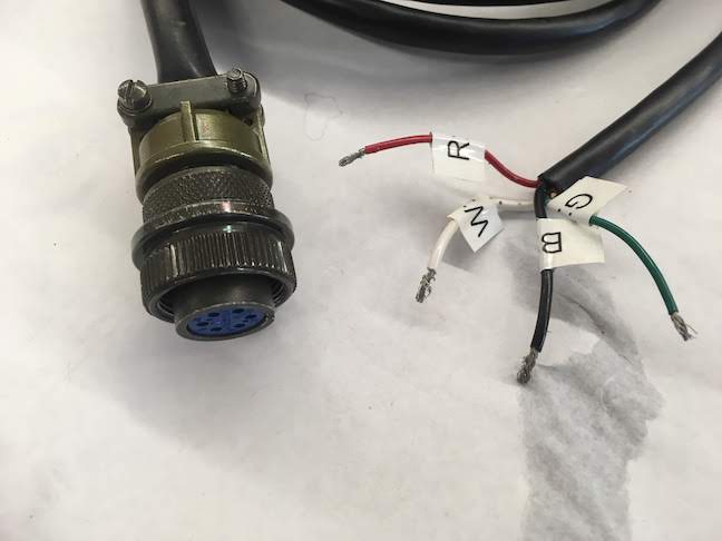
Figure 2.5: 6-pin cable to trigger a sampling sequence to the MUX, using the black (M-) and green (M+) wires, and, to communicate between the MUX and the spectro::lyser using the white (A+) and the red (B-) wires through the RS485 protocol
As illustrated in Figure 2.4, insert the green “M+” wire at the bottom or left connection, and the black “M-” wire at the top or right connection of the ‘Valve’ terminal.
2.2.4 Communications between the MUX and the Spectro::lyser
With this version, the MUX essentially takes control of the Spectro::lyser, by giving impoing the measurement intervals, the 12V trigger signal duration, and its time before measurements, sending it into ‘logger mode’, and writing the fingerprint values onto an SD card. For this we use the RS485 protocol and connections available through the Con::nect Box.
As illustrated in Figure 2.4, insert the white “A+” wire at the bottom or left connection, and the red “B-” wire at the top or right connection of the ‘RS485’ terminal.
2.2.5 The MUX external plugs
The 6-pin and 2-pin wires are plugged in the MUX box itself via the “Auxilliary” and “12 VDC” plugs located on the hinge side of the MUX box as illustrated in Figure 2.4 below.
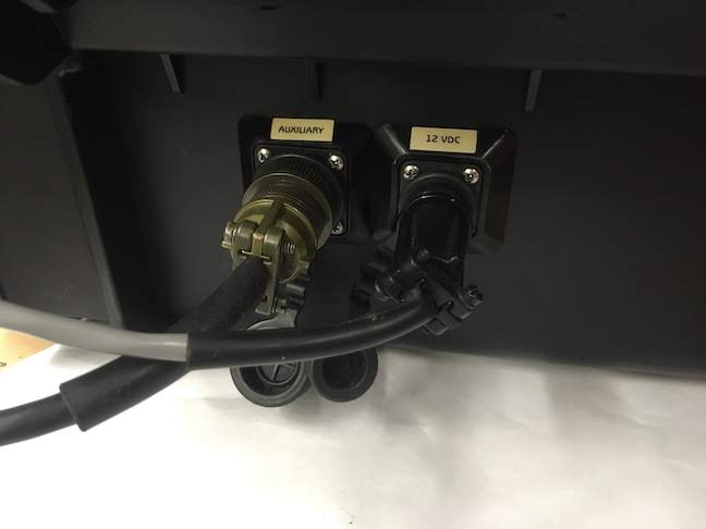
Figure 2.6: External plugs for the 2-pin and 6-pn cables
2.2.6 Control box plugs
Inside the MUX, the control box (Figure 1.1) itself is connected via plugs to the 2-pin and 6-pin wires, and to the solenoid valves. The peristaltic pump is directly connected via its wires thanks to a screw terminal. Normally, there is no need to ever touch at any of these plugs. But should the user need it, it is possible to undo the control box from the rest, and or to change a solenoid valve and easily replace it if needed.
For illustration, the MUX power plugs, as well as the valve and the RS485 plugs on the control box. The 12V coming from the Con::nect Box are plugged in the control box as illustrated in Figure 2.7 below.

Figure 2.7: 12 V Connection between the control box and the external plug
The Signal input and the communication wires coming from the Con::nect Box are plugged in the control box as illustrated in Figure 2.8 below.
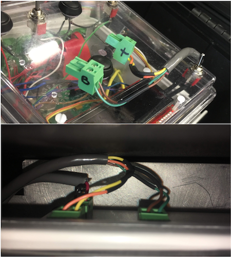
Figure 2.8: 12 V Connection between the control box and the external plug