3 The MUX-sensor functioning
3.1 The general design principles for the MUX
An exert from our first paper (Birgand et al. 2016) summarizes the philosophy behind the MUX:
To remain affordable, the system uses a single high frequency automatic water quality probe as the central analytical instrument to which water from different sampling sites (hereafter, point sources) are pumped via [the MUX]. Our design criteria when constructing the [MUX] system were: (1) to have the capacity of obtaining hourly or sub-hourly samples for measuring multiple point sources, (2) to be able to pump water from the point sources to the probe to overcome at least 3 m of head difference, (3) to be able to run on 12 volts (V) direct current (DC) power for field deployment, and (4) that the coupled [MUX]-water quality probe system functioned entirely automatically. An acceptable compromise for these criteria was to design [the MUX] that enabled sampling from up to 12 point source sites located within [30] m of the central probe. […].
As the in situ field spectrophotometer can only collect one measurement at a time on fixed time intervals, we designed and built [the MUX] to sequentially pump and purge water from each point source to the probe, in synchrony with the probe measurements, and cycle through the sequence of measurements to obtain at least hourly time resolution of data collection at each source. To maintain the water quality probe’s capability of measuring small suspended particle concentrations, we chose 3.18 mm internal diameter flexible tubing as a sampling conduit of water from the point source to the probe, fitted with 1.5 mm mesh screens at the source […]. Consequently, the coupled [MUX]-water quality probe system is well suited for applications where the source sampling volume is not limited and does not affect the process or system studied.
3.2 The different parts of the MUX-sensor system
3.2.1 Sampling ports and rinsing solutions
In continuous flow laboratory analytical equipment, the flow in the tubing is unidirectional, and the measuring cuvette is rinsed by the carrier solution and color reagent between samples to essentially eliminate cross-contamination between samples. In our case, although we are using the Spectro::lyser as an in situ laboratory instrument, there is no carrier fluid for rinsing between samples. To minimize cross contamination between samples, the idea we developed was to reverse flow and purge the instrument cuvette from its water instead. This is the reason for using a peristaltic pump. Now water can be purged either to the sampling port or to a port dedicated to waste.
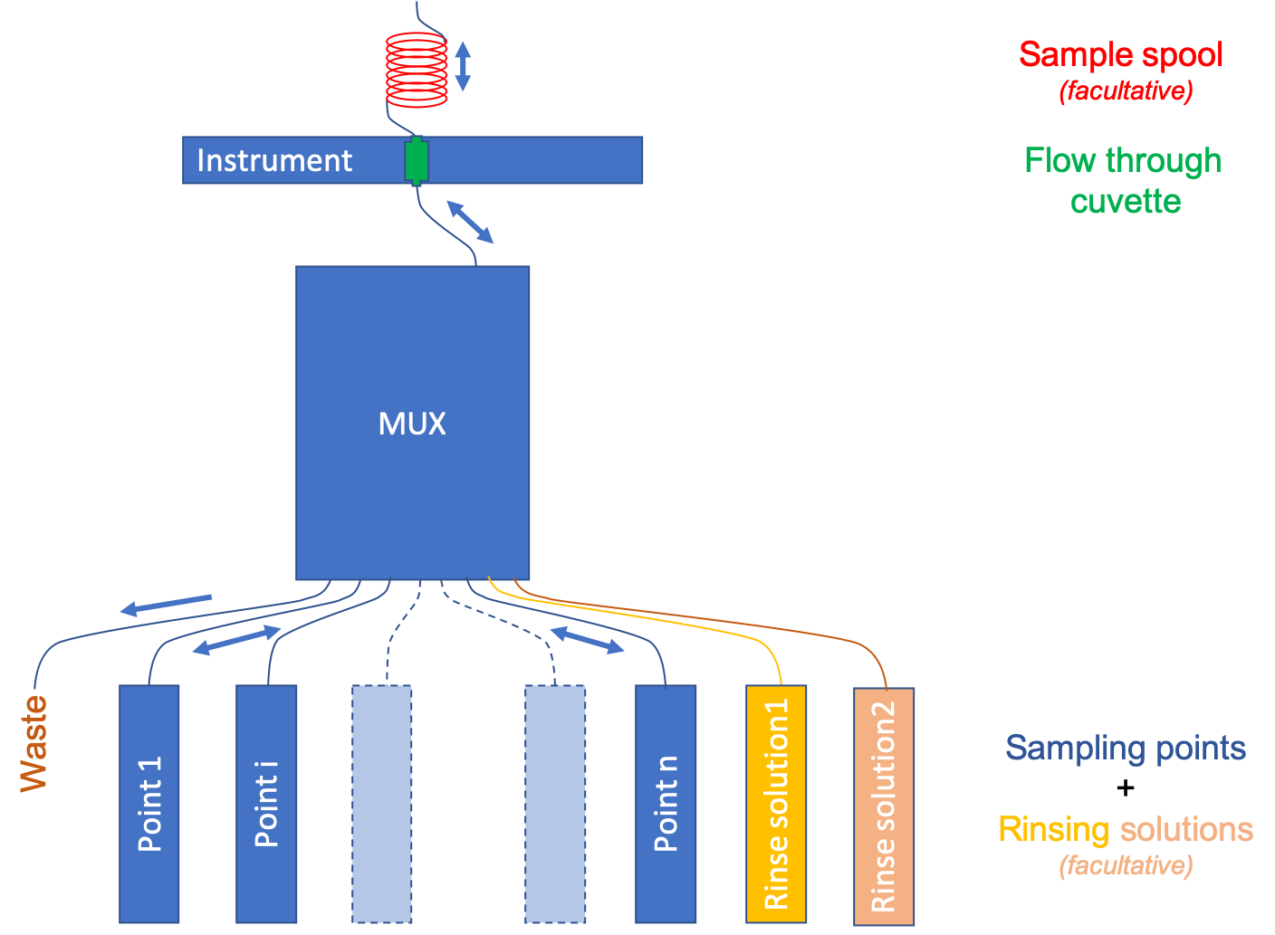
This addresses the cross contamination, but not the fouling that may occur as is often the case on the instrument optics. For this reason, the MUX has an embedded rinsing procedure where it is possible to use acid or other solutions for rinsing. The overall general MUX-sensor setup is summarized in Figure 3.1 below.

Figure 3.1: The MUX in relationship with the sampling points, rinsing solutions, the instrument and its flow-through cuvette, and a sample loop
In Figure 3.1 above, n sampling ports are activated, while two of the ports are dedicated to a rinsing solution 1 and a rinsing solution 2. The MUX has 12 sampling ports and a 13th port for waste if desired. The number or rinsing solutions used, therefore reduces the number of available ports for measured points. In the case of Figure 3.1 above, a maximum of 12 - 2 = 10 ports remain available for point sampling.
Sampled water from any sampling point, including the rinsing solutions, can be purged to any port, including the dedicated waste port (port 13 in the MUX box), or the same port used for sampling, or any other port of the user’s choice.
3.2.2 Flow through cuvette
At the instrument, water is pumped through a flow-through cuvette. This allows to pump water beyond the cuvette and allow for rinsing of the whole manifold and of the cuvette with the new sample. We have found that a good practice to minimize cross contamination is to pump water at least 4 times beyond the volume of the cuvette. For use with the Spectro::lyser with a 35 mm opening, we recommend to use the cuvette 1-Q-10/SBTX2-8/10X20 from Starnacell®. It has a 10 mm path length, is made of quartz, which lets the UV light through, and has a large collar, which make cleaning much easier.
3.2.3 Post-cuvette sample spool
Eventually during a measurement campaign, it is necessary to compare the instrument measured concentrations to those of the laboratory. For this, it is sometimes a good idea to add a sampling spool made of tubing curled together. We recommend that the spool allows for large enough a volume corresponding to the one needed for lab analyses, but small enough such that the initial water that has served to rinse the MUX and the cuvette be beyond the spool such that when purging only ‘clean water’ be used for lab sampling.
3.3 Sampling sequences
In the MUX config.txt file (see further details later), the user specifies the desired sampling interval. During initialization, the MUX puts the Spectro::lyser in logger mode, which means that the instrument will, with no live connection to a computer, automatically take measurements at the indicated time interval.
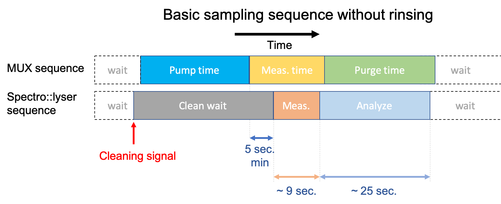
The Spectro::lyser sequence of actions (Figure 3.2) is thus to first send a 12V signal measurable at the ‘valve’ output in the Con::nect box. Again, this is the way the Spectro::lyser deals with fouling. After a given time, referred to as clean wait in the config.txt file and in Figure 3.1, the instrument takes a measurement. A measurement consists in two series of light bursts accompanied by a series of beeps. There are about 9 seconds between the first and the last beep. After that, it takes the Spectro::lyser about 25 seconds to analyze its measurement and make available its absorbance fingerprint and its calculated concentrations (Figure 3.2).

Figure 3.2: The MUX in relationship with the sampling points, rinsing solutions, the instrument and its flow-through cuvette, and a sample loop
3.3.1 Pump and measurement times
The idea with the MUX is to have water to be analyzed in the measuring chamber or cuvette when the Spectro::lyser does its measurement. Once the MUX ‘hears’ the cleaning signal from the Spectro::lyser (Figure 3.2), it starts what we refer to as its sampling sequence. The basic sampling sequence consists in pumping, waiting for the Spectro::lyser measurement, and purging the MUX.
The MUX starts pumping for a pump time defined in the config.txt file for each valve or sampling port. The pump time corresponds to the time it takes for water to go from its sampling point to the instrument cuvette, to which one must add the number of seconds necessary to rinse the equivalent of at least 4-5 times the cuvette volume (Birgand et al. 2016). For some applications, there is no limit on the available volume of water to be analyzed. In these cases, one might want to add 5-6 seconds more on the pump time. For other applications, the available volume might be limited, and it might be necessary to limit the pump time to the strict minimum prescribed here.
The pump time and the clean wait times are thus intrinsically linked. The clean wait time has to be equal to the pump time plus at least 5 seconds to let water in the cuvette ‘rest’ and let all micro air bubbles to stop moving to obtain a reliable and consistent reading by the Spectro::lyser. Keep in mind that there are about 1-2 seconds delay between the cleaning signal and the time when the pumping starts (Figure 3.2).
There are two important additional things to realize here:
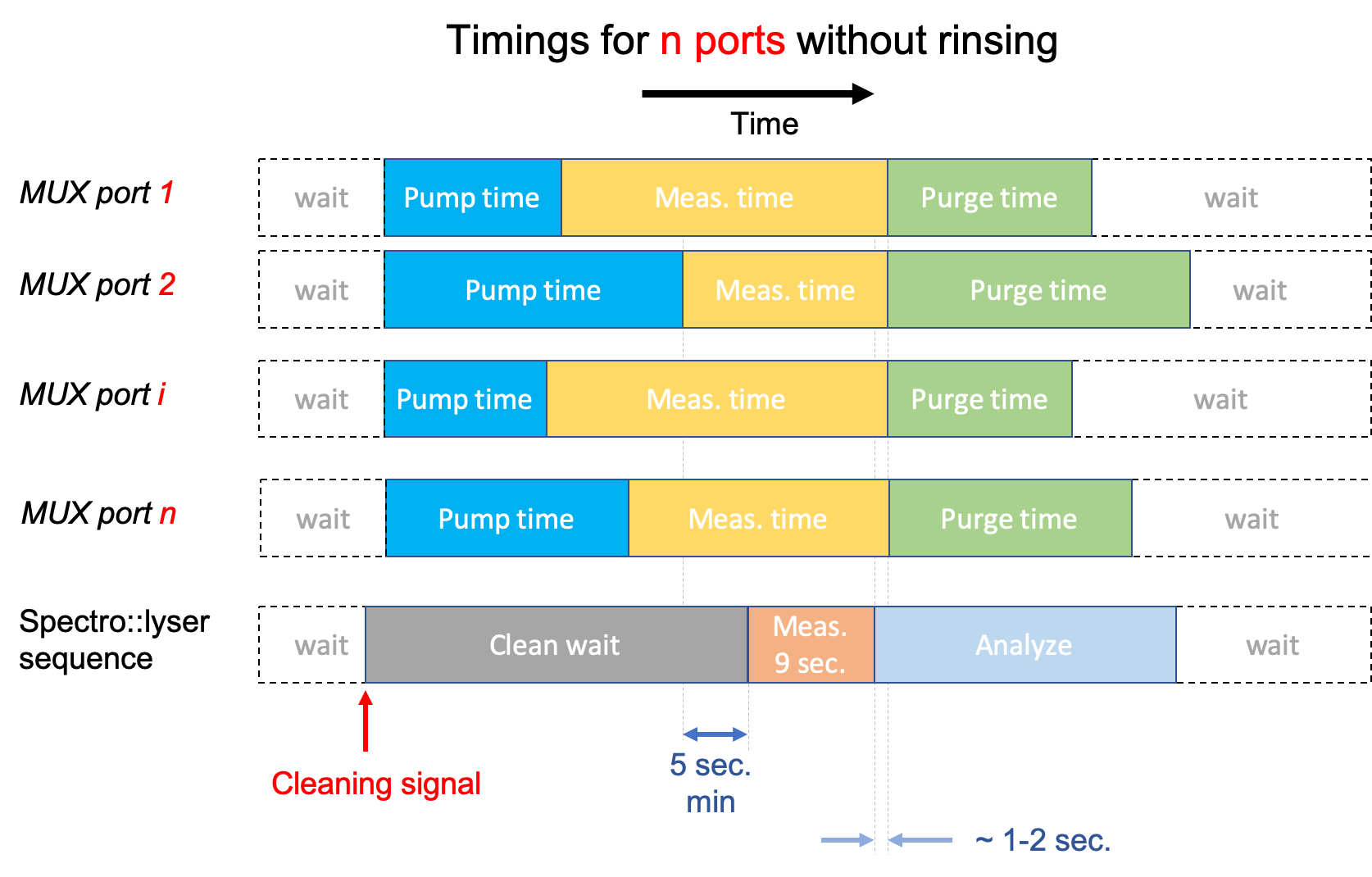
In reality, the pump time may vary from sampling point to the next as it is preferable to pump the least amount of time per port to save energy and pump tubing. The pump time for each port is defined in the config.txt file. However, the clean wait time corresponds to a parameter from the Spectro::lyser, and the same value applies to all sampling points. As a result, the clean wait time must correspond to the longest pump time + 5 seconds (Figure 3.3).
Because it always takes the same amount of time between the cleaning signal and the last beep of the Spectro::lyser measurement, and, because the pump time may vary from one sampling point to the next, the (on the MUX side) sum of pump time + the MUX measurement time should also be the same and be equal to (on the Spectro::lyser side) the clean wait time + the 9 sec. of measurement time + at least 2 seconds past the last measurement (Figure 3.3).
As a result, the pumping time and the measurement time from the MUX must be adjusted (in the config.txt file) accordingly for each sampling point as illustrated in Figure 3.3

Figure 3.3: Adjusting the pumping times and measurement times of the MUX to match the sequence of events of the Spectro::lyser
3.3.2 Purge port and times
The MUX purge time corresponds to the time needed to purge, at least, the cuvette and the MUX valve manifold (Figure 1.1). The purge valve and the purge time is defined in the config.txt file. Depending on the application, the user might want:
- to purge the line that was just used for sampling all the way, in which case, we recommend to use the pump time and add 3-4 seconds to make sure the line is rid of as many droplets as possible.
- to purge to a waste port (port 13 is the dedicated port for that but any port or valve can be used). In that case, the purge time may be much shorter as in all likelihood the line to waste will be much shorter. The idea here is to save energy and the lifetime of the peristaltic pump tubing.
3.3.3 Sampling sequence with automatic rinsing
Our experience with the Spectro::lyser has suggested that a rinsing system be put in place to keep optics or cuvette fouling at a minimum. For this we have designed an embedded automatic rinsing sequence that takes place right after the purging of the basic sampling sequence. For this it is possible in the config.txt file to define one or several rinsing sequence. For each rinsing sequence, one defines in the config.txt file, the port from which the rinsing solution will be sampled and will be purged, the pumping time, and the purging time for the defined rinsing sampling and purging ports, and the number of seconds the rinsing solution will stay in the cuvette.
We have found that when water is sampled from areas where reduced conditions prevail, chemical fouling in the form of iron and manganese precipitate may occur. In these cases, we have found that rinsing using 5% HCl acid solution or an oxalic acid solution (~15 mg L-1) left in the cuvette for 1 min greatly reduced the amount of fouling. We have also found that in some cases rinsing with DI water is enough. In this case, the amount of time DI water stays in the cuvette does not matter as much and can be just a few seconds. We recommend that a rinsing sequence that uses acid should be followed by a second rinsing sequence that uses DI water.
The timings for the rinsing sequence are defined in the config.txt file and the number of rinsing sequences are also defined in the same file. The rinsing sequence(s) automatically take(s) place after the purging of the basic sampling sequence, and does not require a cleaning signal from the Spectro::lyser to take place as illustrated in Figure 3.4 below.

Figure 3.4: The MUX basic sampling sequence followed by an automatic rinsing sequence
3.4 Sampling cycle
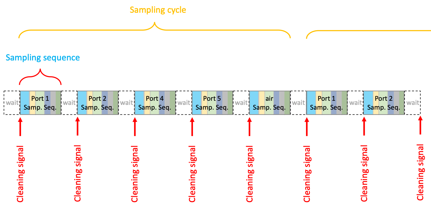
A sampling cycle is the name we have given for a series of sampling sequences that occur on a recurrent basis. For example, if the user has ports 1, 2, 4, and 5 being sampled, a sampling cycle will have a sampling sequence corresponding to port 1, followed by a sampling sequence corresponding to port 2, etc., until the last sampled port, in our example, a sampling sequence for port 5. This would make for the basic sampling cycle. However, we do recommend that the user adds in the sampling cycle, either air or DI water as an easily recognizable ‘tracer’ measurement in the time series of fingerprint from the Spectro::lyser. In our example, a sampling cycle would thus be: “port 1, port 2, port 4, port 5, air” or “port 1, port 2, port 4, port 5, DI”. This sampling cycle repeats itself indefinitely (Figure 3.5). The example below only considers 4 sampled points, because there was not enough space for illustration. However, with one rinsing solution, and using air as a measurement tracer, a sampling cycle can have up to 11 sampled ports (12 minus the port used for rinsing). With two rinsing solutions, and using air as a measurement tracer, a sampling cycle would have up to 10 sampled ports (12 minus the 2 ports used for rinsing). In the latter case, one of the rinsing solutions would likely be DI water, which could also be used as the measurement tracer instead or air in the sampling cycle. In that case, a sampling cycle would still have up to 10 sampled ports (12 minus the 2 port used for rinsing, knowing that DI is used both for rinsingn and as a measurement tracer).

Figure 3.5: The MUX sampling sequences for ports 1, 2, 4, and 5, included into sampling cycles in which an air measurement has been inserted
The advantage of inserting air or DI water in the sampling cycle is that in addition to the aid it provides to identify each cycle in the fingerprint time series, it also gives an estimate of the fouling of the cuvette or the optics. To insert and air measurement in the sampling cycle, the user can use ‘port 13’ in the config.txt file as it is used for waste and is therefore open to the atmosphere. To insert an DI measurement, the user has to have a dedicated port sampling DI from an container with enough DI volume to cover the field visit intervals.
References
Birgand, François, Kyle Aveni-Deforge, Brad Smith, Bryan Maxwell, Marc Horstman, Alexandra B Gerling, and Cayelan C Carey. 2016. “First Report of a Novel Multiplexer Pumping System Coupled to a Water Quality Probe to Collect High Temporal Frequency in Situ Water Chemistry Measurements at Multiple Sites.” Limnol. Oceanogr. Methods 14 (12): 767–83. https://doi.org/10.1002/lom3.10122.